tl;dr: I’m building a machine that produces “interesting” shadowscapes. This installation is scheduled to be showcased as part of a cooperation with Michael Johansson and Oliver Ruf at the Vita Ladan Gallery in Sweden in August 2026. The following text serves as a work-in-progress documentation of the build.
What is the WLM?
The “Wandering Landscape Machine” is a concentric arrangement of silhouettes mounted on rings. When illuminated appropriately, it produces dynamic shadowscapes on a central, static tableau. These shadows can then be transferred into music, images and 3D geometry.
Michael and I have utilized these shadow images multiple times for various projects and installations (for example, see our Skopéin installation here). These shadowscapes as 2D images can be used as a basis to generate 3D objects, create music, and drive interesting visual data. The machine plays with motifs I explored extensively in my dissertation, for instance, the machine-generated shadows reference the typical circa-1800 concept of how (artistic) imagination was processed: by transforming witnessed events that are then imprinted into cognition as “shadow images” that need to be rather transformed (not translated) when they are reproduced.
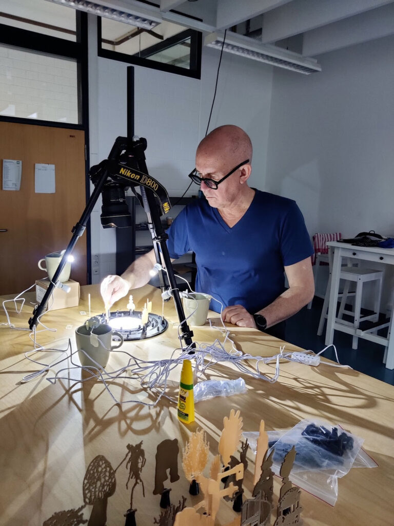
Experimenting with the small scale 3D-printed prototype of the Wandering Landscape Machine at the Media Aesthetics Lab (Bonn-Rhine-Sieg University of Applied Sciences)
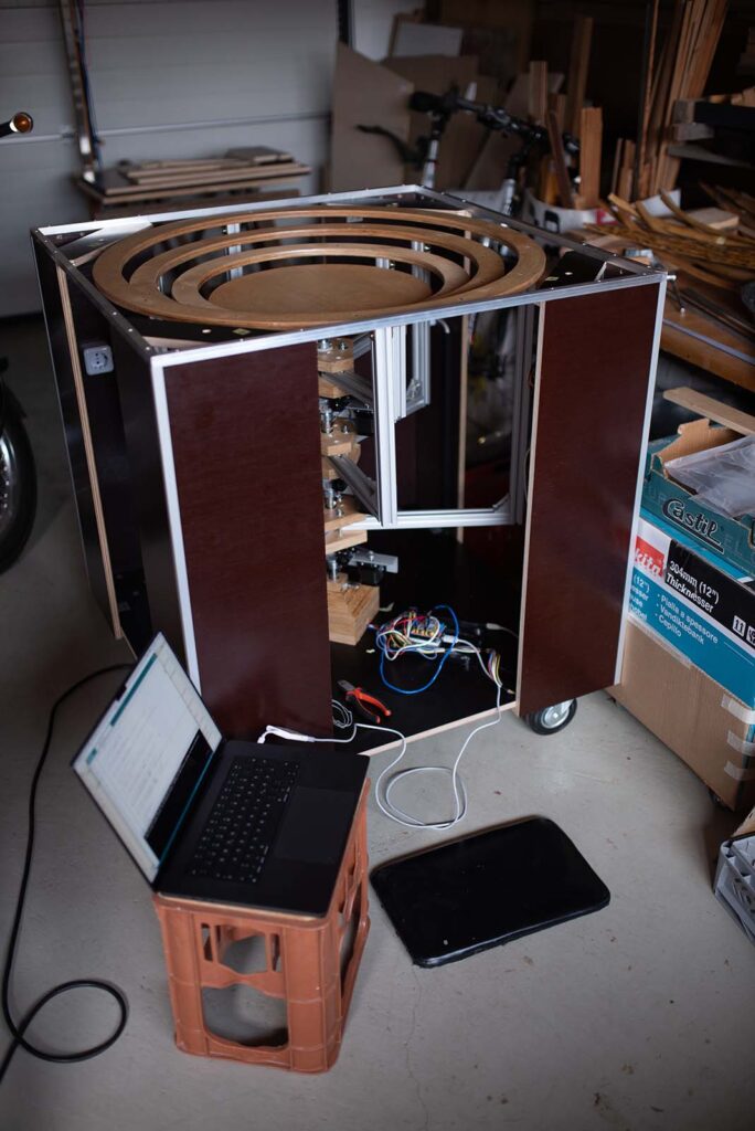
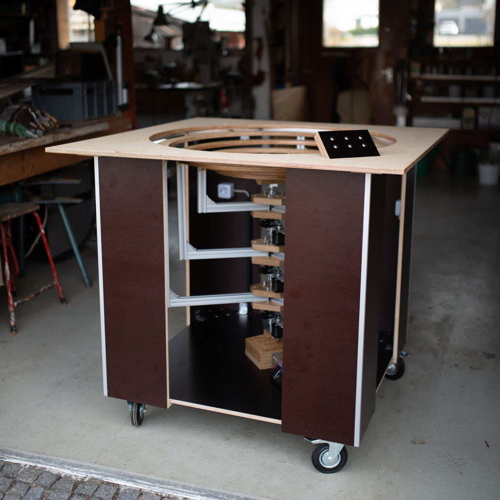
Up until now, this machine has only existed as a purely virtual 3D model and a fairly small 3D-printed prototype. For the upcoming exhibition at the Vita Ladan Gallery in Sweden, however, it needs to be scaled up significantly. The goal is to allow visitors to control the rotation of the rings themselves while generating a captivating, large-scale shadowscape in the center. Below, I’ll try to break down the workflow, share some insights and pitfalls, and show plenty of pictures from the workshop where we are bringing this machine to life.
Concept & Mechanics
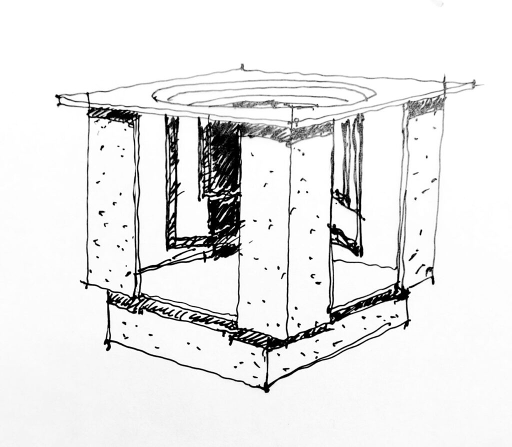
The initial sketches were done with pen and paper (and a bit later using Procreate and Adobe Fresco on the iPad). Since the machine is a collaborative effort between Germany (Andi Siess) and Sweden (Michael Johansson), we needed strong visual references to work on ideas together over Zoom.
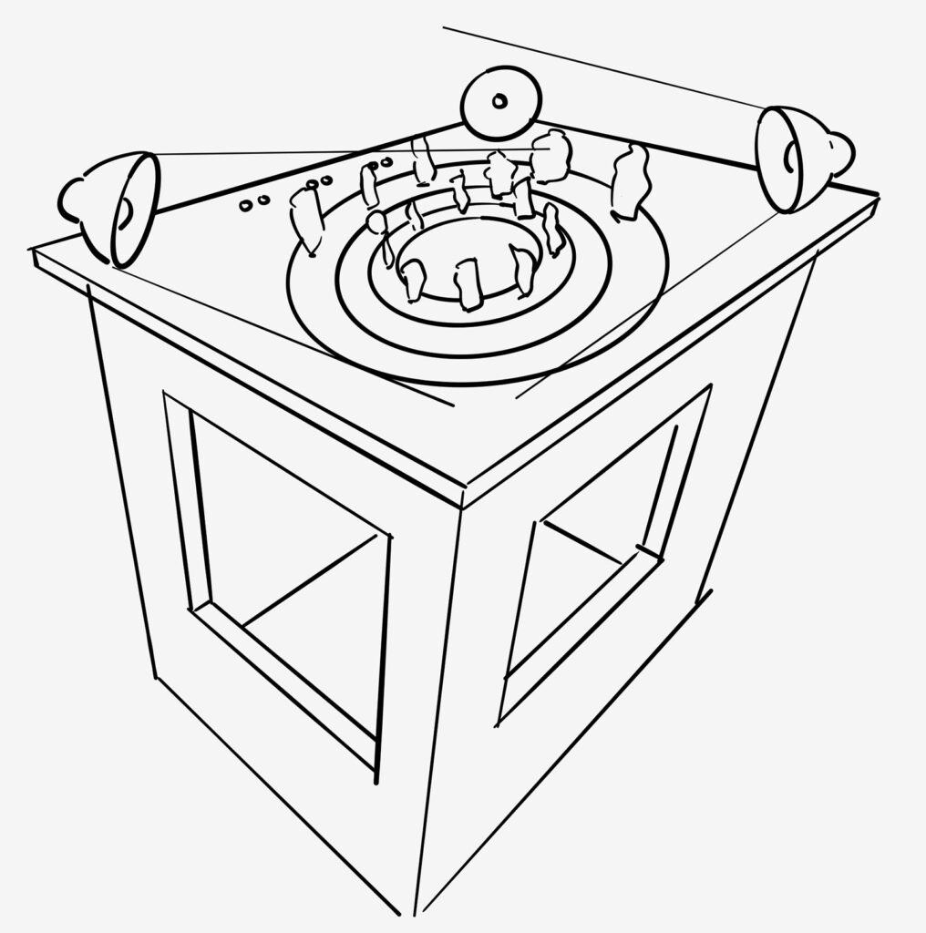
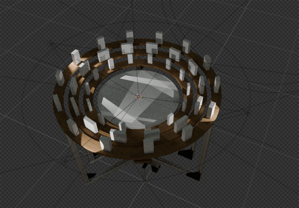
We moved from sketches to early raytracing experiments in Blender to get a rough estimate of the light cones and luminosity. Because we are building a physical machine, we are bound by the laws of physics – meaning the characteristics and limitations of the physical light fixtures have significant structural consequences.
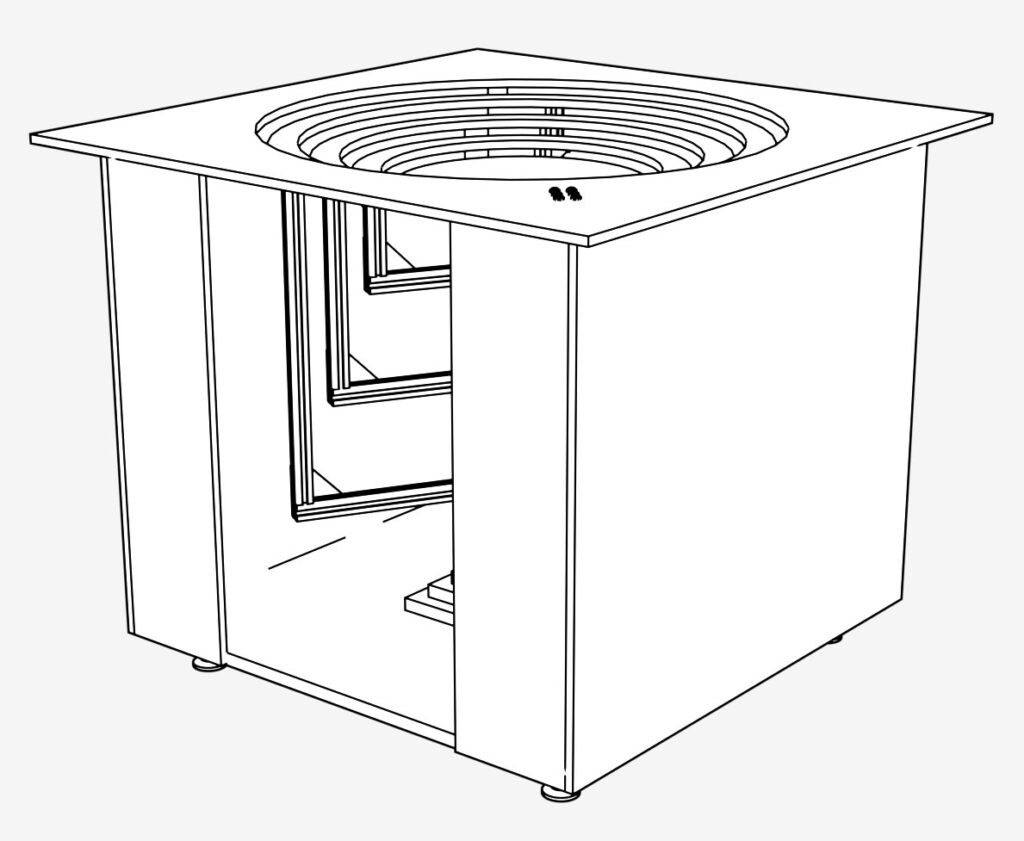
A major mechanical challenge was designing a system that allows three concentric rings to be rotated freely and independently via motors, while the innermost circle (the tableau where the shadows land) remains completely stationary.
Initially, we toyed with the idea of using a planetary gear system or ring gears with roller bearings. We ultimately scrapped these ideas, largely because we knew we’d never hit the required manufacturing tolerances with the tools available to us.
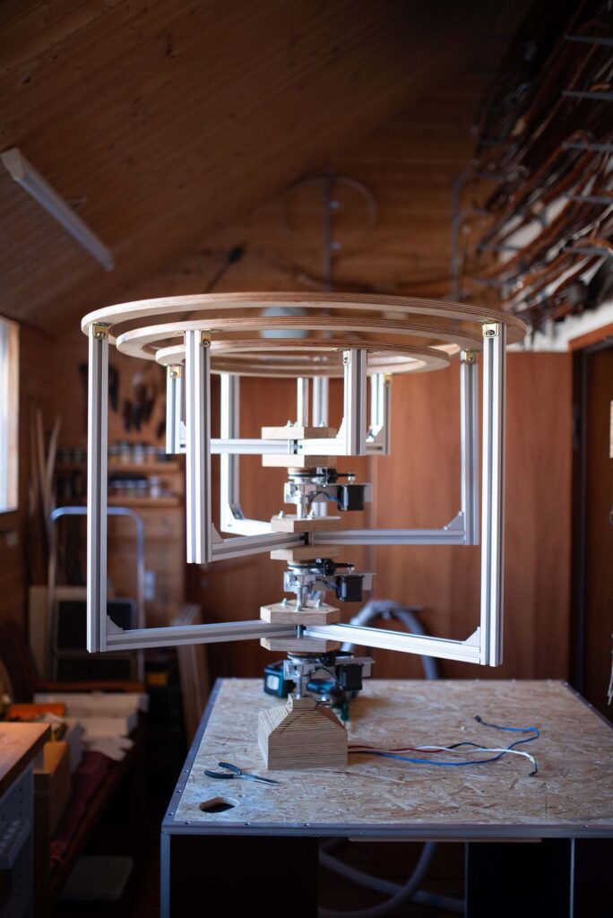
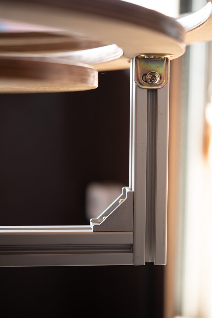
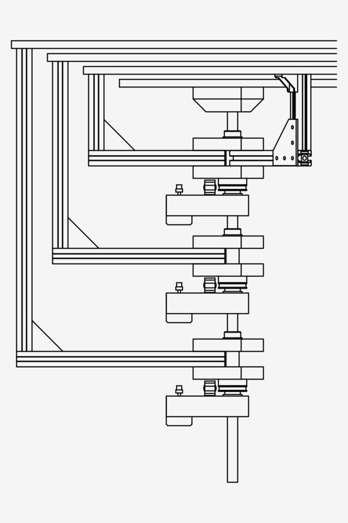
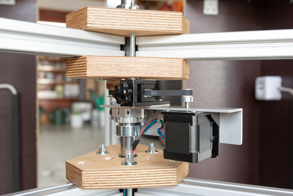
The winning solution was to use a central axis housing three separate “packages,” each featuring outrigger arms to hold the rings. This central axis needs to be hollow to route the necessary power and control cables for the individual motors.
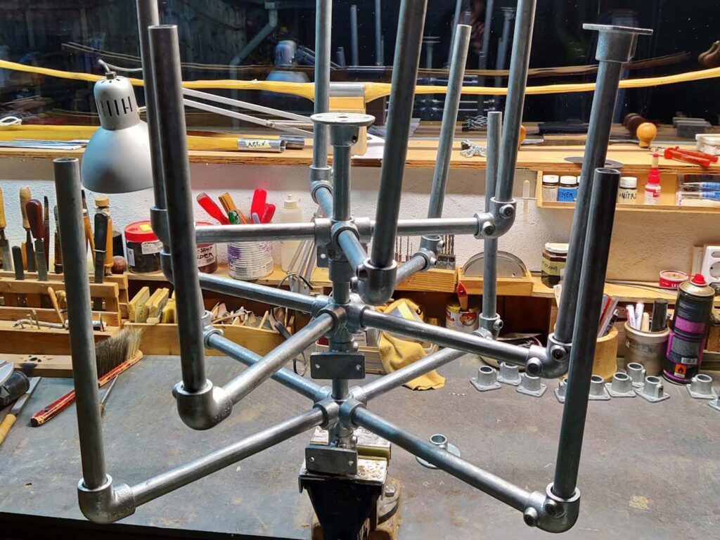
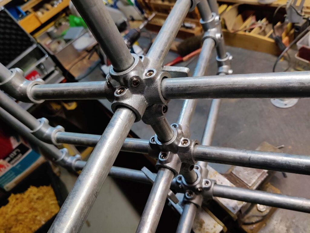
At first, I envisioned a framework made of standard pipes and pipe fittings—mostly because there are so many off-the-shelf parts available. A standard X-cross fitting seemed perfect for letting the outrigger “packages” rotate around the axis. Unfortunately, this approach failed. The manufacturing tolerances of these commercial fittings weren’t anywhere close to what we needed for smooth rotation; the boreholes were simply too large and irregular.
After a lot of brainstorming, we decided to engineer a custom solution using wood, plastic, and aluminum.
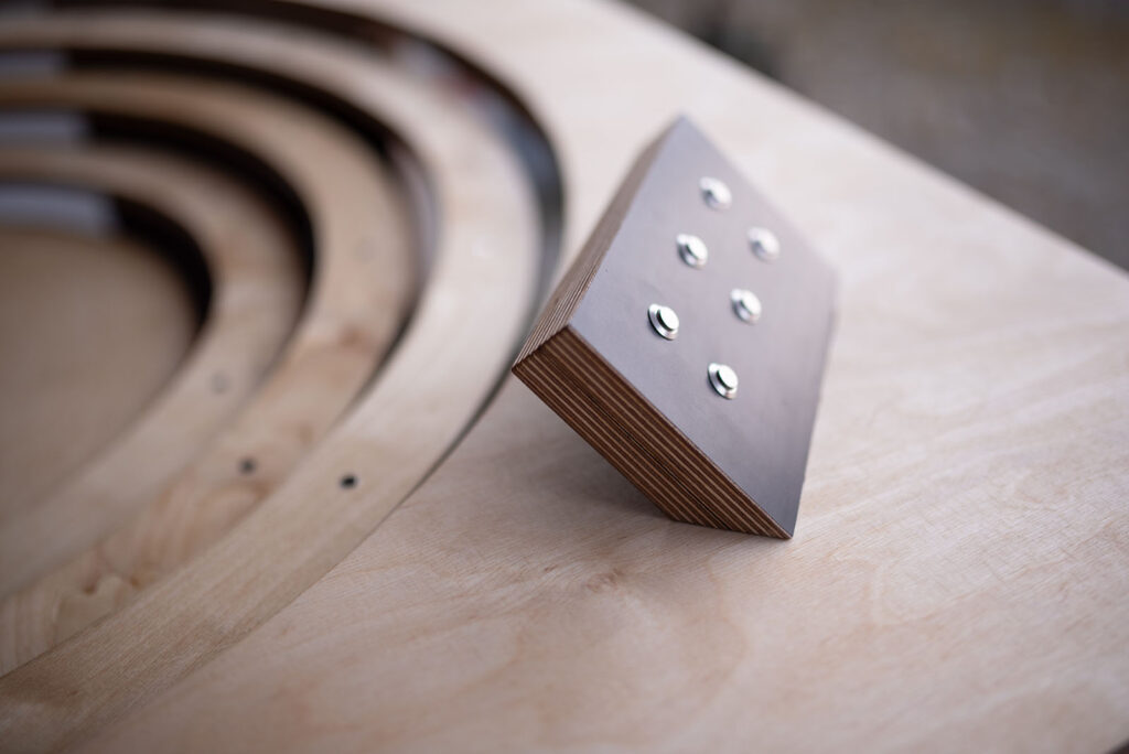
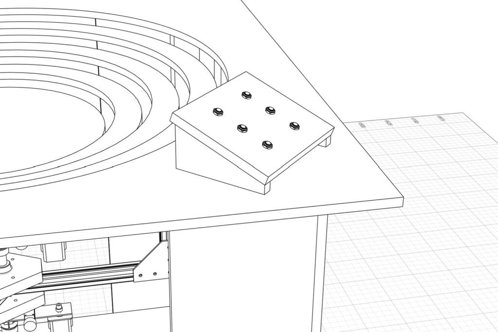
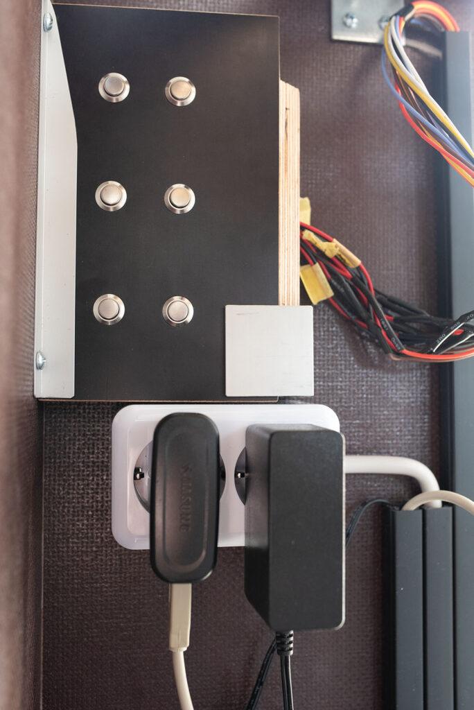
Additionally, we wanted visitors to be able to control the rotation themselves. To facilitate this, we designed a control panel with six buttons arranged in pairs, allowing users to select and control the rotation of each ring independently.
CAD
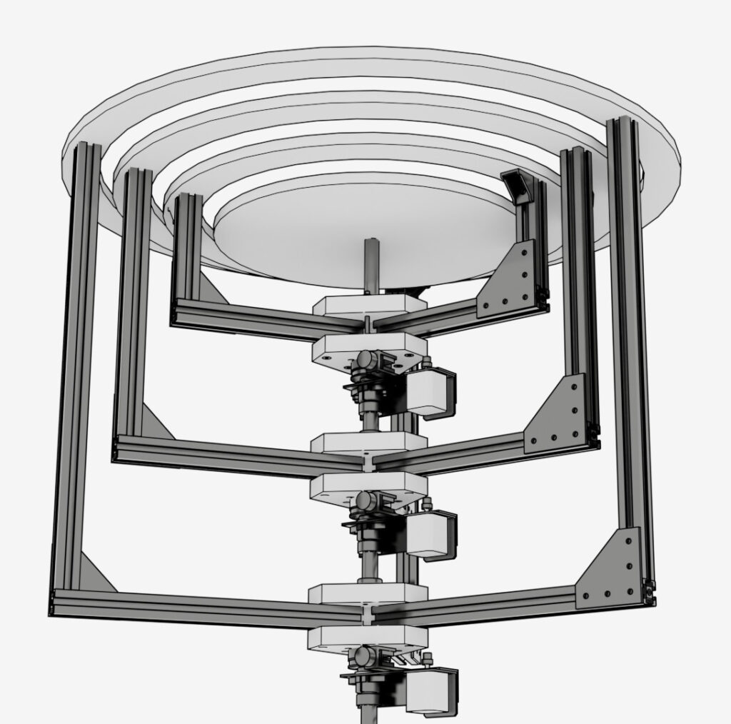
For the first time, I didn’t use a generic 3D modeling tool like Blender or Cinema 4D for the mechanical planning. Instead, I switched to Autodesk Fusion and FreeCAD to design dimensionally accurate parts. Since I didn’t have a ton of experience in mechanical engineering and apparatus construction, Fusion was an incredibly valuable tool for catching design flaws early on and pivoting accordingly.
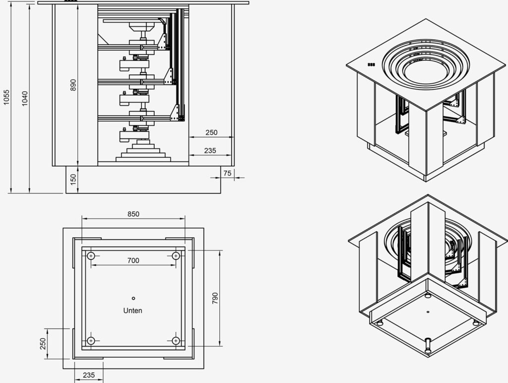
This workflow also allowed us to easily generate and print drill templates, cross-sectional drawings, and fine-tuned details.
Detail Planning
As construction progressed, a multitude of detail-oriented challenges popped up. A few examples:
Routing Cables: To feed the Harwin connectors of the stepper motors into the hollow axis, we had to mill elongated slots into the shaft. These slots had to be as small as possible to avoid compromising the structural integrity of the axis (which bears the entire rotating load of the three rings, arms, and motors).
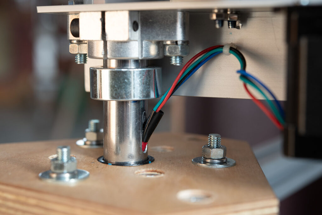
Cable Management: The wiring between the axis and the motors had to be heavily optimized to ensure no dangling cables could get caught in the lower rotating assembly.
Belt Tension: The timing belt tension had to be dialed in perfectly to prevent slipping without over-stressing the motors. We ended up sourcing off-the-shelf parts originally intended for 3D printers, which worked perfectly here.
Arduino Features & 220V Electrical Setup
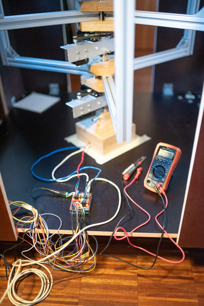
The rotation of the rings is fully motorized. The brains of the operation is an Arduino Uno paired with a CNC Shield. This setup drives three Nema 17 stepper motors, each controlled by a DRV8825 stepper driver equipped with a heatsink. While the steppers could theoretically handle a 2A current, I’m capping them at about 90% of their maximum rated load to reduce strain.
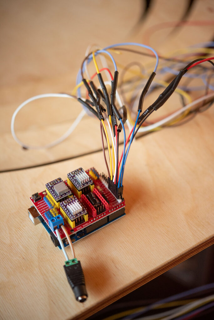
In my naïve optimism, I assumed the Arduino code would be a breeze: six buttons, three motors—sounds straightforward. In reality, the Arduino sketch has ballooned to over 450 lines of code (including documentation). Part of this is because I hijacked the CNC shield’s pins to process button presses (which isn’t what they were designed for). The other reason is that I had to build in a lot of self-protection routines.
Experience tells me that gallery and museum visitors aren’t exactly gentle with interactive installations. To handle potential user errors, I implemented a few safeguards:
- If multiple buttons are pressed simultaneously, the code only registers the first one and ignores the rest. If two are hit at the exact same millisecond, a (pseudo-)randomizer breaks the tie.
- After every button press, the system enters a 300ms sleep mode before accepting new inputs.
- Since the buttons are analog, I wrote a rudimentary debouncing script to avoid torturing the motors and drivers with noisy inputs (i.e. by incomplete button presses). Additionally, the motor startup is delayed by 2000 µs after a button press to allow sufficient voltage to build up in the coils.
If no interaction occurs for two minutes, the system enters an “Idle Mode.” The rings will start rotating automatically and randomly to draw attention back to the machine. This mode instantly breaks the moment a button is pressed.
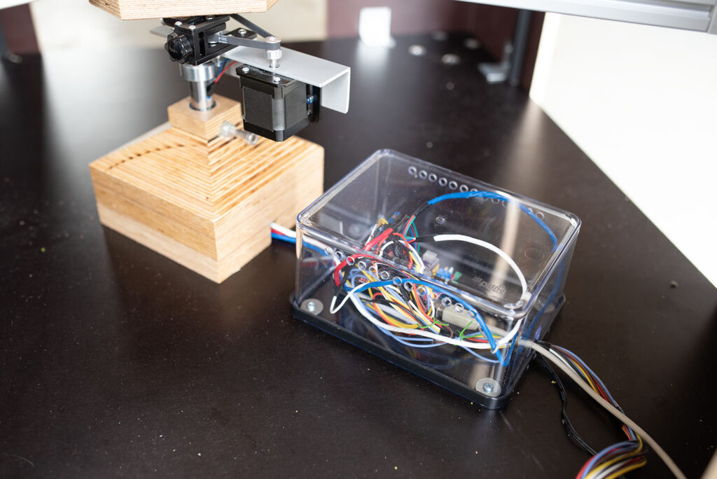
In true DIY fashion, the entire electronics package (Arduino, CNC Shield, motor drivers) is housed inside a transparent plastic food storage container mounted to the bottom of the machine. We drilled a few ventilation holes so the driver heatsinks can properly dissipate heat.
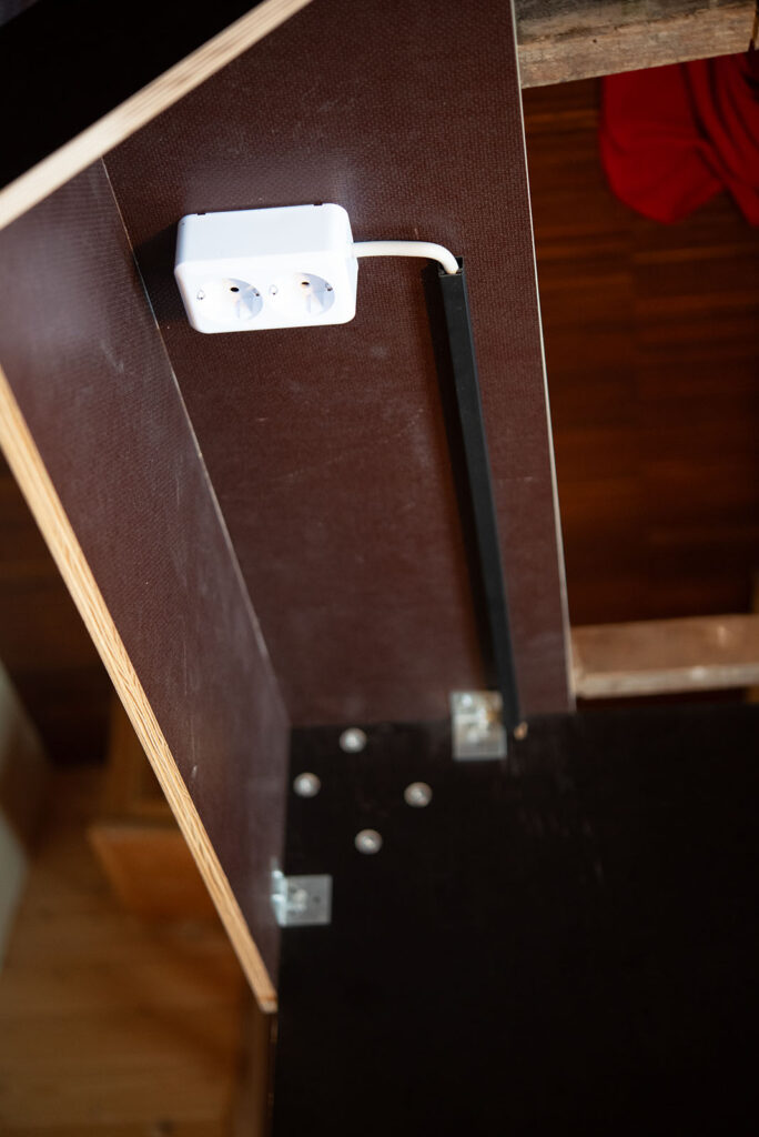
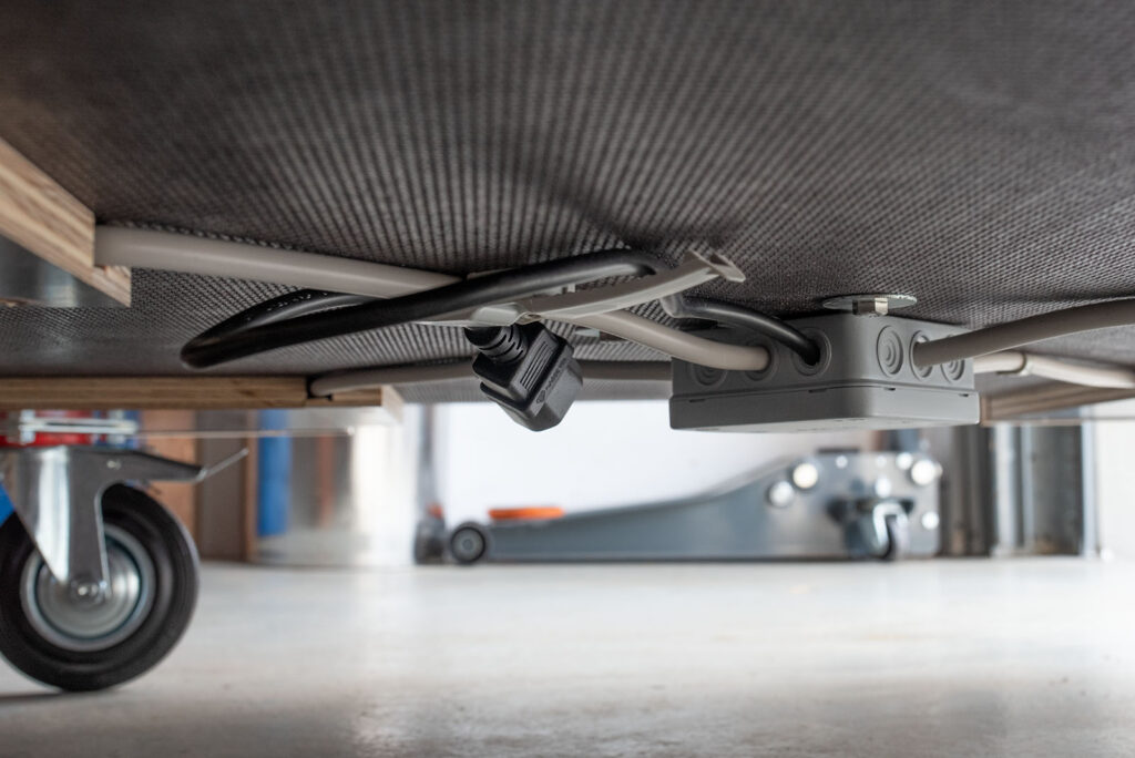
For power, we installed a hidden 220V sub-distribution box safely underneath the main chassis, which branches out to all four sides of the structure (i.e. the “box”).
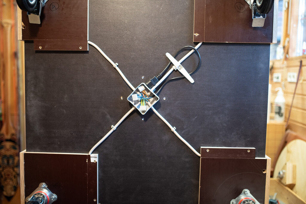
Each side features a standard German Schuko power outlet with full grounding so we can easily plug in lights. One side features a double socket that provides USB power for the Arduino and 12V for the CNC shield.
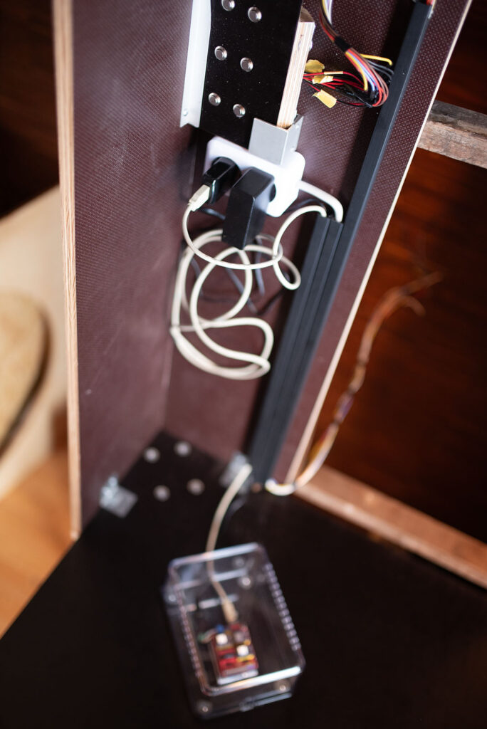
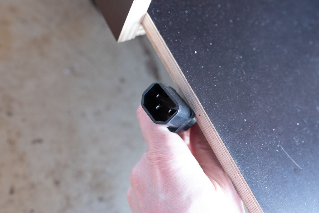
This 220V setup connects to the mains via a standard IEC C14 connector (the kind used for desktop computers). The logic here is future-proofing: the machine will likely travel to countries with different wall plug standards. By using a standard IEC inlet, we can simply swap out the power cable to match the local grid without messing with bulky travel adapters (as long as the grid provides 220/230V).
Iterative Processes
Despite all the precise CAD planning, hitting the workshop floor revealed that certain designs were either impossible or incredibly difficult to fabricate.
We also had new ideas as we built, meaning the machine was constantly evolving. I rigidly fed these physical changes back into the CAD model, ensuring we always had an accurate “digital twin.” This made generating parts lists simple and gave us a clear overview of our progress.
Early version of the machine: Only one viewing slot on the side, furniture glides instead of wheels and a flat switch panel
Case in point: An earlier design of the main chassis had far fewer viewing slots on the sides and sat on wooden feet, which we later swapped for adjustable furniture glides. Neither worked out. In the final version, the 95 kg (210 lb) machine sits on heavy-duty casters, making transport exponentially easier.
Transporting the Machine
Because the machine is being built in Bavaria but is destined for Sweden (and hopefully other galleries beyond), logistics and transport were major design factors.
For shipping, the overhanging tabletop can be removed and replaced by a custom transport lid. Both the tabletop and the lid use the same hex socket screws, meaning the whole thing can be swapped using a single Allen key.
Since the rings and central axis are only anchored at the bottom of the chassis, the rings need to be secured to prevent wobbling and twisting during transit. To solve this, we carved a custom block out of XPS foam (Styrodur). This block wedges tightly between the rings and the transport lid, securing the rings and giving the central axis crucial top-down stability during transport/shipping.
Finally, since the visitor control panel is mounted to the standard tabletop, we designed a quick-release system. The entire control panel can be detached without tools and without unplugging the 12 data cables and stowed safely in a dedicated slot inside the main chassis.
Storage of the control panel during transport inside the main structure
Testing & Lighting
Even with high-end raytrace simulations, it is incredibly hard to virtually replicate the physical nuances of light and, specifically, shadow casting.
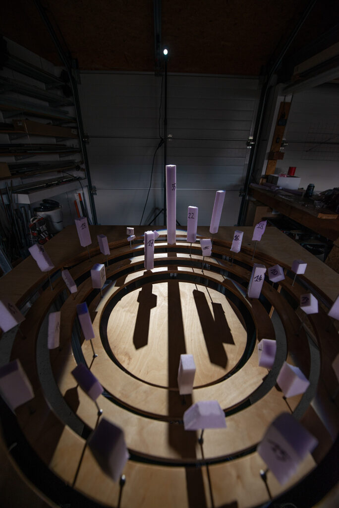
We are currently running physical tests with various fixtures. The tricky part isn’t just picking the type of light (diffuse vs. directional), but figuring out exactly where to position the fixtures in physical space. Placement dictates the required size of the silhouettes, making an experimental, trial-and-error approach the only way forward.
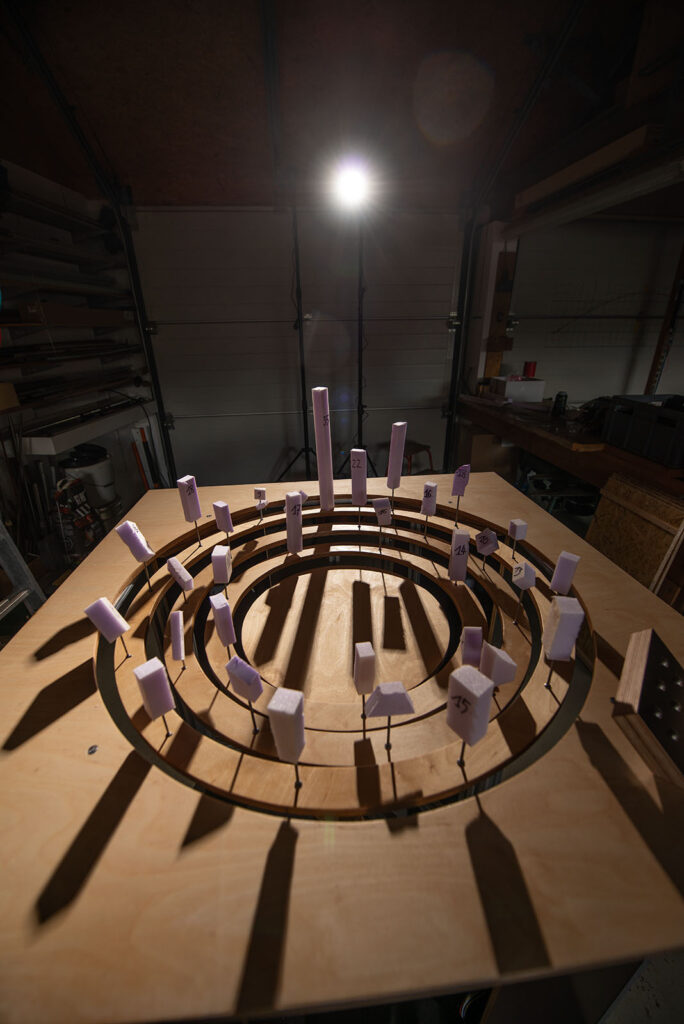
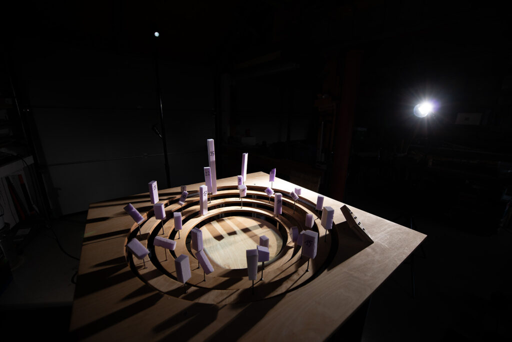
To test this, we placed various XPS foam cubes on the rings, marking them with their respective heights, and started moving lights around the room.
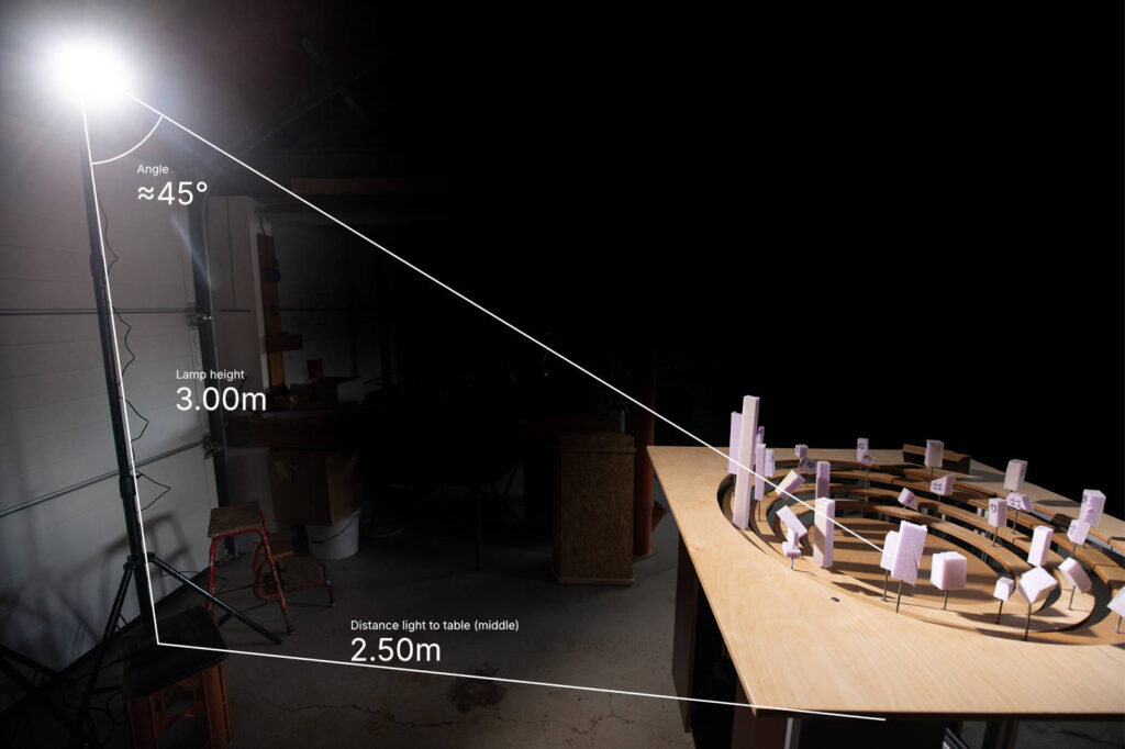
We quickly learned that our original plan – using a very shallow light angle by placing the lights low to the ground – resulted in incredibly boring shadows. Instead, we found a first sweet spot: placing the lights relatively far from the table, hitting the silhouettes at a 45° angle with highly directional beams.
Originally, we wanted lights mounted directly to the table itself to allow for variable positioning. We briefly tested an LED work light meant for industrial lathes, but it was a flop. Currently, we are getting great results testing a compact video light (Amaran COB 60d S – pros: incredibly bright, dimmable, Bowens mount for modifiers) and a cheap theatrical pinspot meant for disco balls (Eurolite LED PST-12W 6000K Spot – pros: cheap, compact, sharp directional beam, built-in optics/aperture) that are placed further away from the table.
Right now, these are just for evaluation. For the final exhibition, we plan to rig at least three light sources to generate the complex, overlapping shadowscapes we’re aiming for.
Acknowledgement
A lot of the wood- and metalworking as well as a lot of detail engineering was done with the great help of my dad Simon. Without his state-of-the-art workshop, his knowledge and his ideas this project would not have been possible. Thank you so much!
This project is funded by Volkswagen Foundation.